Searching for vulnerabilities in IoT devices: Case of CVE-2022-46527 (Part 1) - DEEP
Searching for vulnerabilities in IoT devices: Case of CVE-2022-46527 (Part 1)
14 March 2023
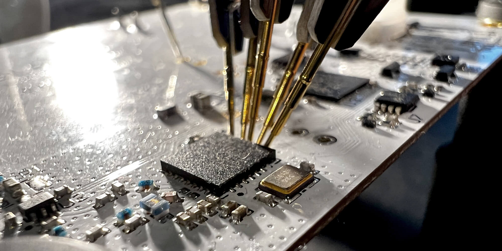
The use of connected objects is becoming increasingly widespread, whether for private needs such as home automation or for business needs such as tracking lorries. Being connected, this type of equipment can pose risks to their users.
In order to ensure customers’ security, the COS team has led assignments to search for vulnerabilities in this type of equipment. This publication is the first in a series and addresses the case of discovering a 0-day vulnerability on one of them. The case study will be divided into two parts. The first part shows the environment setup to analyse the equipment, and the second part will discuss the discovery of CVE-2022-46527 – details of which are still under embargo at this time.
What is a connected object composed of?
Connected objects can be used for a variety of purposes. This can range from reading information, such as temperature or location, to environmental actions such as lighting. A connected object is composed of several parts:
- The power supply
- The network component
- The controller
- The sensor/actuator
The different types of controllers
There are mainly two types of controllers [1]:
- microcontrollers (MCUs)
- microprocessors (MPUs)
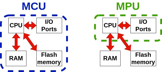
Figure 1: Difference between MCUs and MPUs
MCUs are the most self-contained with the key components they need to function: a processor (CPU), volatile memory (RAM), and non-volatile memory (ROM). They are simpler to integrate, consume less power and have a lower operating speed. In addition, MCUs have little RAM and ROM so they are more suitable for simple use. This type of controller is often used with connected objects that take simple measurements and which can be used for several years without needing to change the battery.
For more intensive use, such as image processing equipment, MPUs are used, but they are more complicated to integrate, as the ROM and RAM must be integrated separately on the electronic circuit in addition to the MPU. This type of controller is more power-hungry, but their higher operating speed and increased ROM and RAM allows them to handle more complex tasks.
Discovery of the target connected object
Connected objects can be used to collect several pieces of information: noise level, temperature, humidity, brightness and presence. The product reference is not yet disclosed, as a responsible disclosure procedure is in progress.
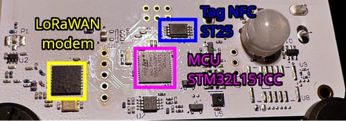
Figure 2: Components on the electronic board
The circuit consists of an STM32L151CC MCU, a LoRaWAN modem and an NFC tag from STMicroelectronics. For the NFC tag, the reference cannot be found on its exposed side after testing. The pinout appears to match the manufacturer's ST25 range.
This MCU’s reference tells us that the architecture of the processor is ARM, which allows us to analyse the content of the firmware more easily.
Firmware recovery
The fact that it is a microcontroller (MCU) means that the contents of the internal flash memory are not directly accessible, unlike MPUs where the flash memory is separate, so:
There are several ways to recover the firmware used by the connected object. STM’s microcontrollers have a debug mode that can be used with an ST-Link adapter. There are also different bootloaders enabling the firmware stored on the internal flash memory to be downloaded. For example, there is the "DFU_UPLOAD" bootloader command via USB DFU.
However, to protect their equipment and intellectual property, the manufacturers can enable flash memory read protection, disable debug mode and disable the bootloader on external interfaces.
In the case of the equipment in question, the debug mode seems to be disabled.
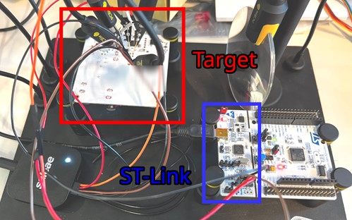
Figure 3: Attempt to debug using the ST-link
A Saleae logic analyser was used to listen to the traffic between the equipment and the debug interface.
Despite the attempts on the debug interface, there was no response from the microcontroller.

Figure 4: Use of a logic analyser to monitor the traffic between the ST-link and the microcontroller
In addition, the pins for selecting the boot mode are locked. Obtaining the firmware directly from the connected object is not possible with the means available.
The manufacturer offers the firmware on its website. It should be noted that the manufacturer offers an adapter to be able to make the updates. In this study, the firmware found on the manufacturer's website was used.
Once the firmware is downloaded, the firmware can be loaded into a disassembler that knows the architecture used.
Here, Ghidra was used to analyse the firmware.
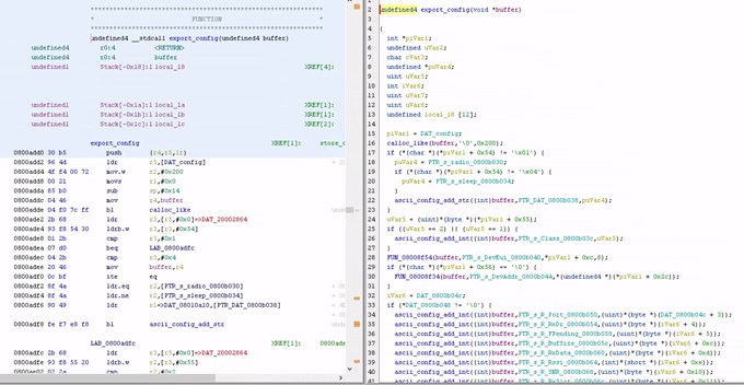
Figure 5: Using Ghidra to analyse the firmware
An analysis of the firmware can reveal risky functions. However, before going into the analysis of the firmware in greater depth, research into the various communication channels and their operation allows us to better focus the search for vulnerabilities on the functions used by the various exchanges with the outside world.
Communication channels
The equipment is configured using an Android application. The application sends a message in NDEF format to the NFC tag. The NFC tag stores the message in its memory. This message contains, on each line, a key and its value.
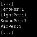
Figure 6: Extract from an Ndef message
The MCU retrieves the data contained in the NFC tag through an I2C interface.

Figure 7: Extract from an Ndef message
After analysis, the MCU takes the configuration contained in the NFC tag and integrates it into the general configuration. There is, however, the special case where the configuration is protected by a PIN. Only the PIN key is taken into account in order to unlock the configuration and obtain a copy in the NFC tag.
Another communication channel is the interface between the MCU and the LoRaWAN modem.
What's next?
In this first part, we were able to explore the equipment on which the vulnerability search is conducted. However, the equipment’s debug and programming mode does not seem to be activated. The processor architecture is ARM and the firmware version is close to the one used by the equipment.
The next step is to explore the different parts of the code that are used in the different communication channels for vulnerabilities.
Contact us
Do you have any questions about an article? Do you need help solving your IT issues?
Contact an expert


Our experts answer your questions
Do you have any questions about an article? Do you need help solving your IT issues?
Other articles in the category Cybersecurity
How do you prepare for NIS2?
NIS2 aims to strengthen the cyber security of critical organisations in Europe. Apply it from January 2025 to avoid fines of up to 2% of your global turnover. Find out in this article what NIS 2 is, who is affected and how to prepare by capitalising on what already exists.
Published on
28 April 2024
DDoS attacks in Luxembourg in 2024
Discover the statistics of DDoS attacks detected in Luxembourg in 2024 by POST Cyberforce.
Published on
31 March 2024
DDoS attacks in Luxembourg in 2023
Discover the statistics of DDoS attacks detected in Luxembourg in 2023 by POST Cyberforce.
Published on
15 February 2023


